Configuring Smoke Control Symbols in Graphics
Scenario
You want to configure and control graphics representing Firefighters' Smoke Control Stations that show the status of associated devices and functions.
- You opened a graphic to edit in Engineering mode.
- You know how to create a graphical command.
- Import or create a background that represents a Control Panel or Geographic Zones. (campus, buildings, floors, etc.)
- In the Graphic Editor, in the View tab, select the Properties and Library Browser panes.
NOTE: You will not need the Element Tree, Depth, Evaluation Editor and other panes, which you can deselect. - In Library Browser, select the Fire_Smoke_Control_HQ_1 library.
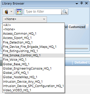
- The smoke control symbols appear in the preview area of the pane.
NOTE: Adjust the zoom factor to 90% or more to better show the symbols. Just use the slider at the bottom right of the pane. - In the list, depending on the unit you want to represent, choose one of the symbols:
NOTE: Hover over the symbol preview to display the full name as a tooltip.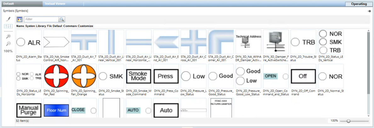
- Drag the desired symbol from the Library Browser into the graphic.
- In System Browser, select the Manual Navigation check box.
- Select Management View.
- In System Browser, locate and expand the fire device subtree.
- Single LED indicator (can be inserted into a container symbol).
Following are examples of individual indicators and how to configure them: - Trouble Indicator symbol: drag pseudo point into TroublePseudo.
- Alarm symbol: based on status propagation, colored red when the object below it is in alarm. Drag the parent node into Object Reference.
- Multiple LED indicator. Below are examples and how to configure them:
- Multiple Indicator symbol: drag pseudo points into NormalPseudo, SmokePseudo, TroublePseudo.
- Pressure Indicator symbol: drag pseudo points into PressureGoodPsuedo and PressureLowPseudo.
- Damper symbol. It represents the status of the physical device using I/O device’s inputs.
- Damper symbol: drag the two status inputs into Closed Switch and Open Switch.
- Fan symbol. Dynamic symbol representing rotating fan,
- Fan symbol: drag pseudo point or switch status into FanPseudo.
- Ownership Symbol. Command to get ownership of the panels with smoke control function.
- Ownership Symbol: Drag the ownership macro previously created with the request commands for the involved panels into the Target and select Command Trigger checkbox. In Command Name, select Execute.
- Building symbol. A container for the custom icon building representing the highest category event using the background color, example: green for no event and red for alarms.
- Building symbol. Configure the substitution animation with the geographic node of the building. Configure the Target section to navigate between buildings.
- Floor symbol. Used in the building graphics to directly open the floor graphics and to show the floors statuses.
- Floor symbol. Configure the substitution with set of floor number. Configure the substitution animation with the geographic node of the floor. Configure the Target section to navigate between floors.
NOTE: In multimonitor configuration, you can configure floor graphics with function FloorGraphic (in Object Configurator) and configure the Flex Client display rules to always open the floors in separate monitor (not building monitor). - Command and status symbols that work by configuring the corresponding pseudo point (without reading it but commanding it) and macro. Following an example.
- Purge command. In Command and Navigation, drag the previously created purge macro into Target and select Command Trigger checkbox. In Command Name, select Execute.
- Purge Status. Drag pseudo point into PurgePseudo substitution.
- From the Home tab of the graphic editor, add any connection lines or additional graphic elements as necessary.
- Click Save
 to save the graphic.
 - Repeat this procedure to add more smoke control symbols as necessary.
- In System Browser, deselect the Manual Navigation check box.